vehicle blackbox dvr user manual

Welcome to the Vehicle Blackbox DVR User Manual! This guide provides comprehensive instructions for setup‚ operation‚ and troubleshooting your device. Discover key functions‚ technical specifications‚ and tips to maximize performance. Designed for both newcomers and experienced users‚ this manual ensures optimal use of your DVR.

1.1 Purpose of the Manual

This manual serves as a comprehensive guide to help users understand and effectively utilize their Vehicle Blackbox DVR. Its primary purpose is to provide clear instructions for setting up‚ operating‚ and troubleshooting the device. Whether you’re a new or experienced user‚ this manual ensures you maximize the DVR’s potential. It covers essential functions‚ technical details‚ and practical tips to enhance your experience. By following this guide‚ you’ll gain confidence in using the DVR’s features‚ resolving common issues‚ and maintaining optimal performance. Designed to be user-friendly‚ this manual is your go-to resource for all aspects of your Vehicle Blackbox DVR.

1.2 Structure of the Manual

This manual is organized into eight main sections to ensure easy navigation and comprehensive understanding of the Vehicle Blackbox DVR. Starting with an introduction‚ it progresses through features‚ installation‚ operation‚ troubleshooting‚ maintenance‚ advanced settings‚ and concludes with final tips. Each section is further divided into subheadings‚ providing detailed information on specific topics. The logical flow allows users to follow step-by-step instructions‚ access troubleshooting solutions‚ and explore customization options. Whether you’re installing the device or optimizing its performance‚ the manual’s structured approach ensures you can quickly find the information you need. This layout is designed to enhance user experience and simplify the learning process for all users.

Features and Specifications of the Vehicle Blackbox DVR

The Vehicle Blackbox DVR boasts Full HD 1080p resolution‚ dual-lens recording‚ night vision‚ and motion detection. It supports loop recording‚ storage expansion‚ and emergency recording for added safety.

2.1 Key Features of the Device

The Vehicle Blackbox DVR is equipped with Full HD 1080p resolution‚ ensuring high-quality video recording. It features a dual-lens design‚ capturing both front and rear views simultaneously. The device includes night vision‚ enhancing low-light recording‚ and motion detection‚ which automatically starts recording when motion is detected. It also supports loop recording‚ allowing continuous recording by overwriting old files. The DVR has an emergency recording feature that saves footage during sudden events. Additionally‚ it offers wireless connectivity for easy file transfer and smartphone app integration. These features make it a reliable and versatile dash cam for drivers seeking security and convenience.

2.2 Technical Specifications

The Vehicle Blackbox DVR boasts a 3-inch LCD screen for clear playback and menu navigation. It supports Full HD 1080p video resolution at 30fps‚ ensuring crisp and detailed recordings. The device is equipped with a 500mAh lithium-ion battery and supports microSD cards up to 256GB for ample storage. It features wireless connectivity for easy file transfer and app integration. The DVR operates on a 5V power supply and includes a built-in microphone for audio recording. It supports AVI and MP4 video formats and is compatible with multiple languages. Designed for durability‚ the device operates in temperatures ranging from -20°C to 60°C‚ making it suitable for various climates. These specifications ensure reliable performance and versatility for drivers.

2.3 Comparison with Other Models

The Vehicle Blackbox DVR stands out among similar devices with its compact design and user-friendly interface. Unlike many dash cams‚ it offers dual-lens functionality‚ capturing both front and rear views simultaneously. Its 1080p resolution surpasses lower-resolution models‚ providing clearer footage for evidence. While other models may lack wireless connectivity‚ this DVR supports Wi-Fi‚ enabling seamless file transfers. Battery life is another strong point‚ with a 500mAh capacity that outperforms many competitors. Additionally‚ its affordable price point makes it an excellent choice for budget-conscious drivers without compromising on quality. These features make it a top contender in the dash cam market‚ offering exceptional value for its price.

Installation and Setup of the Vehicle Blackbox DVR

Mount the DVR on your rearview mirror using the provided rubber mounts. Adjust the position for optimal view‚ insert the memory card‚ and connect the charger. Power on to complete setup.

3.1 Mounting the Device

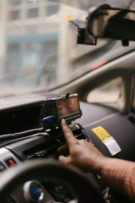
Welcome to the mounting section of your Vehicle Blackbox DVR setup! Securely attach the DVR to your car’s rearview mirror using the provided rubber mounts. Ensure the device is level and tightly fastened for a clear view. For optimal placement‚ position the DVR near the windshield to capture the road ahead. Clean the mirror surface before mounting to ensure a strong grip. If preferred‚ you can also use the adhesive mount for a permanent installation. Tighten all screws firmly to prevent any movement while driving. Once mounted‚ adjust the angle to achieve the best recording perspective. Your DVR is now ready for use!

3.2 Connecting Cables and Accessories

Connect the car charger to the DVR and plug it into your vehicle’s 12V power outlet. Ensure the charger is securely fitted to avoid loose connections. If your model includes a rear camera‚ attach it to the DVR using the provided cable. Insert the memory card into the designated slot‚ ensuring it clicks into place. Connect any additional accessories‚ such as a USB cable for data transfer. Power on the device to verify all connections are functional. For proper operation‚ ensure all cables are tightly secured and routed neatly to avoid obstruction. This setup ensures seamless recording and optimal performance of your Vehicle Blackbox DVR.

3.3 Synchronizing with Rear Camera (if applicable)

To synchronize your Vehicle Blackbox DVR with a rear camera‚ first‚ connect the rear camera cable to the DVR’s designated port. Ensure both devices are powered on and the DVR is in standby mode. Navigate to the menu‚ select the “Rear Camera” option‚ and enable it. Adjust settings like camera angle and brightness for optimal clarity. Test the synchronization by playing back the rear camera feed to ensure proper connection. If issues arise‚ restart both devices and repeat the process. Proper synchronization ensures simultaneous recording from both cameras‚ enhancing your vehicle’s surveillance capabilities. This step is essential for dual-camera models to function effectively. Always refer to your specific model’s instructions for precise steps. Regularly check connections to maintain synchronization.

Operating the Vehicle Blackbox DVR

Power on the DVR using the designated button. Navigate the menu using the OK and R buttons for settings and playback. Start recording automatically or manually. Access emergency recording to capture critical moments instantly. Use the lock button to protect important files from overwrite.

4.1 Powering On and Off

To power on the Vehicle Blackbox DVR‚ press the POWER button. The device will automatically start recording when the car ignition is turned on. If the car is shut off‚ the DVR continues operating for 15 seconds before turning off and saving the last recording. For manual control‚ press the POWER button again to turn it off. Ensure the device is connected to a 5V car charger for proper operation. Avoid using unauthorized chargers to prevent damage. Always power off the DVR before disconnecting it from the power source to maintain functionality and data integrity. Proper power management ensures reliable performance and recording quality. Follow these steps for seamless operation.

4.2 Navigating the Menu System

The Vehicle Blackbox DVR features an intuitive menu system designed for easy navigation. To access the menu‚ press the MENU button. Use the R button to scroll through options and OK to select. The menu includes settings for video quality‚ timestamp‚ and motion detection. Adjust settings by navigating with the R button and confirming with OK. To exit‚ press MENU again. This system ensures quick access to features‚ enhancing user experience. Explore the menu to customize your DVR settings effectively and efficiently. Proper navigation ensures optimal device performance and personalized recording preferences. This user-friendly interface makes it easy to configure your DVR to meet your specific needs.

4.3 Recording and Playback Functions

Your Vehicle Blackbox DVR offers seamless recording and playback capabilities. Press the POWER button to start recording automatically. The device features loop recording‚ which overwrites old files when storage is full. For emergency situations‚ press the LOCK button to save crucial footage. To playback‚ navigate to the PLAYBACK menu using the R button and select files with OK. Videos can also be viewed on a computer via USB. The DVR supports time-lapse recording and video stabilization for smoother playback. Ensure your memory card is properly inserted for optimal performance. This feature-rich system allows you to capture and review your journeys effortlessly‚ enhancing your driving experience with reliable recording and clear playback options;

4.4 Using the Emergency Recording Feature

The emergency recording feature on your Vehicle Blackbox DVR is designed to capture critical moments. Press the LOCK or EMERGENCY button to activate it‚ saving the current recording and preventing it from being overwritten. This function is ideal for accidents or unexpected events. Ensure the device is powered on and a memory card is inserted for this feature to work. The DVR will automatically mark and protect the emergency file. Access these recordings in the PLAYBACK menu under a dedicated folder. Regularly check your settings to ensure emergency recording is enabled‚ providing peace of mind while driving. This feature is a vital tool for preserving important evidence‚ ensuring your safety and security on the road.

Troubleshooting Common Issues

Troubleshooting your Vehicle Blackbox DVR? Common issues include no power‚ no image‚ or rear camera malfunctions. Check power connections‚ format memory cards‚ and adjust settings for resolution.

5.1 Common Problems and Solutions

Experiencing issues with your Vehicle Blackbox DVR? Common problems include no power‚ no image on the screen‚ or rear camera malfunction. Solve these by checking power connections‚ ensuring the device is fully charged‚ and formatting memory cards. For no image‚ adjust the lens focus or reset the device. If the rear camera isn’t syncing‚ ensure proper cable connections and synchronization. Resetting the DVR to factory settings can often resolve software-related issues. Always refer to the manual for detailed troubleshooting steps and ensure firmware is up-to-date for optimal performance.

5.2 Resetting the Device

To reset your Vehicle Blackbox DVR‚ locate the reset button (usually found on the underside or rear of the device). Use a small pin or SIM card tool to press and hold the button for 5-10 seconds. The device will power off and restart‚ restoring factory settings. Note that resetting will erase all custom settings but will not delete recorded files. This process is useful for resolving software-related issues or starting fresh with default configurations. Ensure the device is powered on before attempting a reset. After resetting‚ refer to the manual to reconfigure your preferred settings for optimal performance.

5.3 Updating Firmware

To ensure your Vehicle Blackbox DVR performs optimally‚ regular firmware updates are essential. Visit the manufacturer’s website to download the latest firmware version. Save the update file to an empty memory card and insert it into the DVR. Navigate to the menu system‚ select Settings‚ and choose Firmware Update. Follow on-screen instructions to complete the process. Do not interrupt the update‚ as this may cause device malfunctions. Once updated‚ restart the device to apply changes. Regular updates improve functionality‚ add features‚ and fix bugs. Always use the official website to download updates to ensure compatibility and security.

Maintenance and Care

Regularly clean the DVR with a soft cloth to avoid dust buildup. Manage memory by deleting unnecessary files and ensure proper battery maintenance for optimal performance.

6.1 Cleaning the Device

Regular cleaning is essential to maintain your Vehicle Blackbox DVR’s performance. Use a soft‚ dry cloth to gently wipe the exterior and screen‚ removing dust and fingerprints. Avoid harsh chemicals or abrasive materials that may damage the surface. For tougher smudges‚ lightly dampen the cloth with water‚ but ensure no moisture enters the device. Never clean the DVR while it is powered on or connected to a power source. This simple maintenance routine will prevent dust buildup‚ ensure clear visibility‚ and prolong the lifespan of your device. Cleaning regularly is crucial for optimal functionality and video clarity.

6.2 Managing Memory and Storage

Proper memory and storage management ensures your Vehicle Blackbox DVR operates efficiently. Use a compatible SD card (recommended Class 10 or higher) and regularly check its storage capacity. When the card is full‚ enable loop recording to overwrite older files. Avoid using multiple small memory cards‚ as this can reduce performance. Always format the SD card in the device‚ not on a computer‚ to prevent formatting errors. To free up space‚ transfer important files to your computer or external storage before deleting them. For optimal functionality‚ update your firmware periodically and avoid overfilling the storage to maintain smooth recording and playback capabilities.

6.3 Battery Maintenance

To ensure optimal performance and longevity of your Vehicle Blackbox DVR’s battery‚ follow these guidelines. Always use the provided 5V car charger to avoid overcharging or damaging the battery. Store the device in a cool‚ dry place when not in use to prevent overheating‚ which can degrade battery health. Regularly check the battery level indicator on the device to monitor charge status. If the battery drains completely‚ allow it to charge fully before turning it on again. Avoid leaving the device unused for extended periods without charging‚ as this can cause deep discharge and reduce battery life. Proper maintenance ensures reliable operation and extends the lifespan of your DVR.

Advanced Settings and Customization

This section covers advanced customization options for your Vehicle Blackbox DVR‚ including video quality adjustments‚ time-lapse recording setup‚ and motion detection configuration to tailor the device to your needs.

7.1 Adjusting Video Quality Settings

Your Vehicle Blackbox DVR allows you to customize video quality for optimal clarity. Access the Settings menu and navigate to Video Quality. Choose between HD 1080p or lower resolutions to balance detail and storage. Adjust the bitrate for smoother video or sharper images. Select from pre-set options or manually fine-tune settings. Higher frame rates (e.g.‚ 60fps) enhance motion capture. Experiment with these settings to find the perfect balance for your needs. Remember to reboot the device after changes. For more details‚ refer to the manual or online guides for specific model instructions.

7.2 Setting Up Time Lapse Recording

To enable Time Lapse Recording on your Vehicle Blackbox DVR‚ navigate to the Advanced Settings menu. Select Recording Mode and choose Time Lapse. Set the desired interval (e.g.‚ 1 frame per second) to reduce storage usage. This feature is ideal for long-term monitoring. After configuring‚ press OK to save changes. The DVR will capture footage at the specified intervals‚ ensuring continuous recording without filling the memory card quickly. Note that longer intervals may reduce video smoothness. Always test the settings to ensure they meet your requirements. Refer to the manual for additional customization options to optimize your recording experience.

7.3 Configuring Motion Detection

To configure the motion detection feature on your Vehicle Blackbox DVR‚ go to the Advanced Settings menu and select Motion Detection Settings. Enable the feature and adjust the sensitivity levels (low‚ medium‚ or high) based on your preferences. The DVR will automatically start recording when motion is detected‚ ensuring capturing of important events. You can also set the duration of the recording after motion is detected. For added security‚ enable the G-sensor to activate recording during sudden movements or collisions. Test the settings to ensure proper functionality. This feature is ideal for 24/7 monitoring‚ providing peace of mind while your vehicle is unattended. Always check the device’s LED indicators to confirm motion detection is active.

8.1 Maximizing the Performance of Your DVR

To ensure your Vehicle Blackbox DVR operates at its best‚ always position the camera for an unobstructed view. Regularly update the firmware and clean the lens for clear footage. Use a high-quality memory card and avoid overfilling storage. Adjust settings like resolution and motion detection based on your needs. Keep the device charged and avoid extreme temperatures. For optimal night vision‚ ensure proper illumination. Finally‚ review recordings periodically to ensure everything is functioning correctly. By following these tips‚ you’ll enhance reliability‚ video quality‚ and overall performance‚ ensuring your DVR serves as a trusted companion on the road.

8.2 Staying Updated with the Latest Features

Regularly check for firmware updates to ensure your Vehicle Blackbox DVR has the latest features and improvements. Updates often enhance performance‚ add new functionalities‚ and fix issues. Visit the manufacturer’s website or use the device’s built-in update feature. Before updating‚ backup your data and follow the instructions carefully. New features may include improved night vision‚ enhanced motion detection‚ or expanded storage compatibility. Stay informed about software releases and user feedback to make the most of your DVR. By keeping your device updated‚ you ensure it remains reliable and continues to meet your evolving needs on the road.

boss tu3 manual

The BOSS TU-3 is a renowned chromatic tuner pedal, celebrated for its precision, durability, and versatility. Widely used by professionals and hobbyists alike, it excels in both live performances and studio environments, offering reliable tuning with advanced features like flat tuning options and high-brightness mode. Its robust design and user-friendly interface make it a favorite among musicians, ensuring accurate tuning and durability under demanding conditions.

1.1 Overview of the BOSS TU-3 Chromatic Tuner

The BOSS TU-3 is a benchmark chromatic tuner pedal designed for precision and versatility. It supports chromatic, guitar, and bass tuning modes, with flat tuning options for dropped tunings. Featuring the Accu-Pitch function, it provides clear visual confirmation of accurate tuning. The high-brightness mode ensures excellent visibility in any setting, while its sturdy construction withstands rigorous use. Compatible with 7-string guitars and 6-string basses, the TU-3 is a reliable tool for musicians, offering intuitive operation and robust performance for both live and studio applications.

1.2 History and Evolution of the BOSS TU Series

The BOSS TU Series began with the TU-2, a groundbreaking tuner that set industry standards. The TU-3 builds on this legacy, introducing enhanced features like flat tuning options and high-brightness mode. Its evolution reflects advancements in technology and musician feedback, solidifying its status as a reliable tool for precise tuning. The TU-3’s robust design and versatility have made it a staple in the music industry, favored by professionals and hobbyists for its accuracy and durability in both live and studio settings.

1.3 Why the TU-3 is a Favorite Among Musicians

The BOSS TU-3 is a favorite among musicians due to its exceptional accuracy, durability, and ease of use. Its chromatic tuning capability supports guitars, basses, and extended-range instruments. The Accu-Pitch function provides clear visual confirmation, while the high-brightness mode ensures visibility in any setting. Its compact, pedal-friendly design integrates seamlessly into effect chains, making it ideal for both live performances and studio sessions. Additionally, its robust construction withstands rigorous use, earning it a reputation as an indispensable tool for professionals and hobbyists alike.

Key Features of the BOSS TU-3

  • Chromatic tuning for guitar, bass, and extended-range instruments.
  • Flat tuning options for alternate tunings.
  • Accu-Pitch function for clear visual confirmation.
  • High-brightness mode for enhanced visibility.
  • Support for 7-string guitars and 6-string basses.

2.1 Chromatic Tuning for Guitar and Bass

The BOSS TU-3 provides precise chromatic tuning for both guitar and bass, accommodating all standard and alternative tunings. Its wide tuning range ensures accurate pitch detection, making it ideal for 6-string guitars and 4/5/6-string basses. Whether in standard tuning or drop tunings, the TU-3 delivers reliable performance with clear visual feedback, ensuring your instrument sounds its best in any musical setting. This versatility makes it a go-to choice for musicians across genres and skill levels.

2.2 Flat Tuning Options

The BOSS TU-3 offers versatile flat tuning options, allowing adjustments up to six semitones below standard pitch. This feature is ideal for musicians who frequently use alternate tunings or play 7-string guitars and 6-string basses. The tuner supports flat tuning in all modes, ensuring precise adjustments without compromising accuracy. With its intuitive interface, you can easily select and store flat tuning settings, making it a reliable tool for both stage and studio use. The bright LED display provides clear visual feedback, ensuring accurate tuning even in low-light environments.

2.3 Accu-Pitch Function for Visual Confirmation

The Accu-Pitch function on the BOSS TU-3 provides a clear visual confirmation when your instrument is in tune. When activated, the tuner’s LED indicators light up steadily, ensuring precise tuning accuracy. This feature is particularly useful in noisy environments or for musicians who rely on visual cues. The function can be toggled on or off, offering flexibility for different performance settings. The bright LEDs ensure visibility, making it easy to confirm tuning even on dimly lit stages or in recording studios. This feature enhances the TU-3’s reliability as a professional-grade tuner pedal.

2.4 High-Brightness Mode for Better Visibility

The BOSS TU-3 features a high-brightness mode that enhances the visibility of the LED indicators, making it ideal for use in bright stage lights or outdoor performances. This mode increases the tuner’s display intensity, ensuring that the tuning status is always clear. Activated through the settings menu, this feature is a significant upgrade from its predecessor, the TU-2, and is powered by an AC adapter or battery. The high-brightness mode ensures that musicians can tune accurately and efficiently, regardless of the lighting conditions, making the TU-3 a versatile and reliable choice for professionals and hobbyists alike.

Installation and Setup

Unboxing the BOSS TU-3 reveals a sturdy pedal with clear instructions. Connect your guitar or bass to the INPUT jack to power it on. Power options include battery or AC adapter. Initial setup involves calibration, ensuring accurate tuning. The process is straightforward, with the manual guiding users through each step for optimal performance. Proper installation ensures reliable functionality, making the TU-3 ready for use in any musical setting.

3.1 Unboxing and First Impressions

Unboxing the BOSS TU-3 reveals a compact, robust pedal designed for durability. The package includes the tuner, a user manual, and a battery. First impressions highlight its sturdy construction and intuitive interface. The pedal’s sleek design and clear LED display inspire confidence. Initial setup is straightforward, with the manual providing clear guidance. Musicians appreciate the pedal’s portability and reliability, making it a dependable tool for both live and studio use. The TU-3’s professional-grade build and user-friendly features immediately establish it as a valuable addition to any musician’s setup.

3.2 Connecting the TU-3 to Your Guitar or Bass

To connect your guitar or bass to the BOSS TU-3, locate the INPUT jack on the tuner pedal. Plug your instrument’s cable into this jack, which will power on the tuner. Ensure the pedal is powered either by a battery or an AC adapter. Press the pedal switch to activate the tuner, and the CHECK indicator will light up. Play a note on your instrument; the TU-3 will automatically detect the input. Select the appropriate tuning mode (chromatic, guitar, or bass) using the MODE button. For 7-string guitars or basses, adjust the flat tuning settings as needed. The Accu-Pitch function provides visual confirmation when in tune, and the high-brightness mode enhances visibility. The TU-3 mutes the output signal during tuning. If issues arise, refer to the manual for troubleshooting connectivity problems or resetting to factory settings.

3.3 Power Options: Battery vs. AC Adapter

The BOSS TU-3 offers flexible power options for convenience. It can be powered using a single 9-volt battery, providing portability for gigs and rehearsals. Alternatively, an AC adapter (sold separately) ensures consistent power without draining the battery. The TU-3 consumes 85mA in high-brightness mode, making the AC adapter a reliable choice for extended use. Battery life is decent, but the AC adapter is recommended for stable, long-term operation. Both options ensure the tuner remains functional, catering to different performance and setup needs.

3.4 Initial Setup and Calibration

Setting up the BOSS TU-3 is straightforward. Connect your guitar or bass to the INPUT jack, which powers on the tuner. Press the pedal switch to activate it, and the CHECK indicator will light up. Calibration is automatic, but you can adjust settings like flat tuning or brightness mode as needed. The tuner retains settings in memory, ensuring consistency. If desired, factory settings can be restored by following the manual’s reset procedure, ensuring optimal performance tailored to your musical needs.

Using the BOSS TU-3

The BOSS TU-3 offers seamless operation for guitar and bass tuning. Connect your instrument, press the pedal to activate, and navigate modes via intuitive buttons for precise tuning.

4.1 Basic Tuning Steps

The BOSS TU-3 simplifies tuning with clear steps. Connect your guitar or bass to the INPUT jack, which activates the pedal automatically. Press the pedal switch to power on, and the CHECK indicator will light up. Pluck a string and tune your instrument until the needle aligns with the desired pitch. Use the STREAM/CENT button to toggle between chromatic and string modes for precise adjustments. The Accu-Pitch function provides visual confirmation when tuning is accurate, ensuring quick and reliable results every time.

4.2 Selecting Tuning Modes (Chromatic, Guitar, Bass)

The BOSS TU-3 offers three tuning modes: Chromatic, Guitar, and Bass. Chromatic mode allows tuning to any note, while Guitar mode is optimized for standard tuning (E-A-D-G-B-E). Bass mode supports low-frequency notes for bass guitars. To switch modes, press and hold the MODE button until the desired mode is displayed. The pedal automatically adjusts its tuning range based on the selected mode, ensuring accurate tuning for any instrument. This versatility makes the TU-3 ideal for guitarists and bassists alike, whether in standard or alternative tunings.

4.3 Navigating the TU-3 Menu and Settings

Navigating the BOSS TU-3 menu is straightforward, with intuitive controls for accessing various settings. Use the MODE button to cycle through tuning modes (Chromatic, Guitar, Bass), while the STREAM/CENT button adjusts the tuning meter’s sensitivity. The pedal also allows customization of flat tuning settings and high-brightness mode for enhanced visibility. Settings are saved automatically, ensuring convenience during live performances or studio use. The menu’s simplicity ensures quick adjustments, making the TU-3 user-friendly for musicians of all skill levels. This ease of use contributes to its popularity among professionals and hobbyists alike.

4.4 Using the TU-3 in Live Performance

The BOSS TU-3 excels in live performance settings, offering reliable tuning with its robust design and high-brightness mode for excellent visibility under stage lights. Its silent tuning function ensures no sound is output during tuning, minimizing disruptions. The pedal’s durability and precision make it a favorite among touring musicians, while its intuitive interface allows for quick adjustments. Whether on a bustling stage or in an intimate venue, the TU-3 delivers consistent accuracy, ensuring seamless performances and solidifying its reputation as an indispensable tool for professionals.

4.5 Studio Applications for the TU-3

The BOSS TU-3 is a valuable tool in studio settings, offering precise chromatic tuning for guitars and basses. Its flat tuning options accommodate alternate tunings, while the Accu-Pitch function provides clear visual confirmation. The high-brightness mode ensures visibility in low-light environments, and its silent tuning feature prevents interruptions during recording. Supporting 7-string guitars and 6-string basses, the TU-3’s versatility and reliability make it a trusted choice for studio engineers and musicians, ensuring accurate tuning and seamless integration into any recording workflow.

Advanced Features and Customization

The BOSS TU-3 offers advanced features like flat tuning adjustments and high-brightness mode for enhanced visibility. It also allows customization for 7-string guitars and 6-string basses, ensuring versatility.

5.1 Adjusting Flat Tuning Settings

Adjusting flat tuning settings on the BOSS TU-3 allows for precise tuning down by up to six semitones. This feature is ideal for alternative tunings, providing flexibility for various musical styles.

5.2 Enabling and Using the High-Brightness Mode

The High-Brightness Mode on the BOSS TU-3 enhances visibility in bright environments, making it ideal for stage use. This mode increases the display’s intensity, ensuring clear readability under harsh lighting. To enable it, press and hold the pedal switch while powering on. Note that this mode consumes more power, so using the recommended BOSS AC adapter is advisable to maintain optimal performance. This feature ensures accurate tuning even in challenging conditions, solidifying the TU-3’s reliability for professional musicians.

5.3 Customizing the Tuner for 7-String Guitars and 6-String Basses

The BOSS TU-3 accommodates 7-string guitars and 6-string basses with ease. It supports flat tunings up to six semitones below standard pitch, ideal for modern playing styles. The tuner automatically detects the instrument type, ensuring accurate tuning. For 7-string guitars, it recognizes lower frequencies, while for 6-string basses, it adapts to deeper notes. The flat tuning settings are adjustable via the menu, allowing precise customization. This versatility makes the TU-3 a reliable choice for musicians exploring extended-range instruments or alternate tunings. Its adaptability ensures seamless integration into diverse musical setups.

Maintenance and Care

Regularly clean the TU-3 with a soft cloth to remove dust and dirt. Avoid harsh chemicals or abrasive materials. Store the pedal in a dry, cool place to prevent damage and ensure longevity.

6.1 Cleaning the TU-3

Regular cleaning is essential to maintain the TU-3’s performance and longevity. Use a soft, dry cloth to wipe the pedal’s surface, removing dust and dirt. For stubborn marks, lightly dampen the cloth with water, but avoid harsh chemicals or abrasive cleaners. Gently clean the display and buttons, taking care not to press or damage any components. Never spray liquids directly onto the pedal, as this could harm internal electronics. After cleaning, allow the TU-3 to air dry before use to ensure optimal functionality.

6.2 Replacing the Battery

To replace the battery in your TU-3, first ensure the pedal is powered off. Locate the battery compartment on the underside of the unit and remove the screw to open it. Carefully take out the old battery and insert a new 9V alkaline battery, matching the polarity as indicated. Replace the compartment cover and screw it securely. If using an AC adapter, this step is unnecessary. Always handle batteries with care, avoiding improper disposal to protect the environment. This ensures your TU-3 remains reliable and ready for use.

6.3 Protecting the Pedal from Damage

To maintain the longevity of your TU-3, handle it with care. Avoid applying excessive pressure on buttons or switches, as this may cause damage. Clean the pedal regularly using a soft cloth to prevent dust buildup. Store the TU-3 in a protective case when not in use to shield it from scratches and impacts. During transport, ensure it is securely packed to avoid movement that could lead to damage. By following these steps, you can protect your TU-3 and ensure it remains functional and reliable for years to come.

Troubleshooting Common Issues

Common issues with the TU-3 include no power, display problems, or inaccurate tuning. Check connections, ensure proper power supply, and recalibrate if necessary. Resetting to factory settings often resolves persistent problems.

7.1 No Power or Display Issues

If the TU-3 fails to power on or the display is unresponsive, check the power source first. Ensure the battery is installed correctly or the AC adapter is properly connected. If using a battery, replace it with a fresh one. Verify that no cables are damaged and all connections are secure. Resetting the pedal to factory settings may resolve display issues. If the problem persists, refer to the manual for further troubleshooting steps or contact BOSS support for assistance.

7.2 Inaccurate Tuning or Calibration Problems

If the TU-3 is providing inaccurate tuning or calibration issues arise, ensure the unit is properly calibrated. Reset the tuner to factory settings using the STREAM/CENT button. Verify the flat tuning settings match your instrument’s requirements. Check for external noise interference and ensure the guitar or bass is properly connected. If issues persist, update the firmware or consult the manual for advanced calibration steps. Regularly cleaning the input jack and ensuring a stable power supply can also improve tuning accuracy.

7.3 Connectivity Issues with Guitars or Basses

If experiencing connectivity issues with your guitar or bass, ensure the instrument is properly connected to the INPUT jack. Check for dirt or debris in the jack, as this can disrupt the signal. Use a high-quality cable to minimize interference. Verify the tuner is powered on and in the correct mode (guitar or bass). If problems persist, consult the manual for troubleshooting steps or reset the TU-3 to factory settings. Ensuring a stable power supply and clean connections will help maintain reliable performance.

7.4 Resetting the TU-3 to Factory Settings

To reset the TU-3 to factory settings, press and hold the “STREAM/CENT” button while turning on the power. This restores all settings to their original configuration, including tuning modes and brightness settings. Note that all custom adjustments will be lost. If issues persist after resetting, refer to the manual or contact BOSS support for further assistance. This process ensures the tuner returns to its default state, ready for a fresh setup.

Comparisons with Other Tuners

The BOSS TU-3 stands out for its superior accuracy, high-brightness display, and robust build. It surpasses the TU-2 with enhanced features and remains a top choice among musicians, solidifying its reputation as an industry-standard tuner.

8.1 BOSS TU-3 vs. TU-2

The BOSS TU-3 is an upgraded version of the TU-2, offering enhanced features like high-brightness mode and flat tuning options. It provides greater visibility and versatility, making it ideal for professional musicians. The TU-3 also supports 7-string guitars and 6-string basses, unlike the TU-2. With improved accuracy and a wider tuning range, the TU-3 is preferred by touring pros. Its advanced features and robust build make it a superior choice for demanding performances, solidifying its reputation as an industry-standard tuner.

8.2 BOSS TU-3 vs. Other Popular Tuner Pedals

The BOSS TU-3 stands out among other popular tuners due to its exceptional accuracy, durability, and versatility. Unlike competitors, it offers a high-brightness mode for improved visibility and supports flat tunings up to six semitones. Its compatibility with 7-string guitars and 6-string basses makes it a favorite among versatile musicians. The TU-3’s robust design and intuitive interface ensure reliability under rigorous conditions, making it a top choice for professionals and hobbyists alike. Its feature-rich design and industry-standard reputation set it apart from other tuner pedals on the market.

User Reviews and Feedback

Musicians praise the BOSS TU-3 for its accuracy, durability, and ease of use. Professionals highlight its reliability in live performances, while hobbyists appreciate its intuitive design. Common criticisms include its higher price compared to other tuners, but its robust build and consistent performance make it a worthwhile investment for many players.

9.1 Professional Musicians’ Opinions

Professional musicians consistently praise the BOSS TU-3 for its exceptional accuracy and reliability. Many touring artists rely on its durability and high-brightness mode for clear visibility on stage. The tuner’s ability to handle flat tunings and support for 7-string guitars and 6-string basses makes it versatile for diverse performances. Its buffer circuit is also commended for maintaining tone quality. While some note its higher price, most agree the TU-3’s performance and longevity justify the investment, solidifying its status as an industry-standard tool for professionals worldwide.

9.2 Hobbyist and Beginner Experiences

Hobbyists and beginners appreciate the BOSS TU-3 for its user-friendly design and clear interface. The included manual provides straightforward guidance, helping newcomers master tuning techniques. Many praise the tuner’s ease of use, with features like chromatic tuning and flat tuning options simplifying the learning process. The high-brightness mode is particularly useful for practice sessions in various lighting conditions. While some beginners find the price a bit high, the TU-3’s durability and reliability make it a worthwhile investment for musicians looking to improve their skills and grow as players.

9.3 Common Praise and Criticisms

The BOSS TU-3 is widely praised for its precision, durability, and user-friendly interface, making it a reliable tool for musicians. Many highlight its versatility in handling 7-string guitars and 6-string basses, as well as its flat tuning capabilities. The high-brightness mode is particularly commended for its visibility in various lighting conditions. However, some users note that the manual could provide more detailed explanations for advanced features. Additionally, the price is considered high by a few, though most agree the quality justifies the cost. Overall, the TU-3 is celebrated as a robust and essential tuner pedal.

Additional Resources

Discover more about the BOSS TU-3 through its official manual, online forums, and video tutorials. Visit the BOSS Global Support page for troubleshooting guides and contact information.

10.1 Downloading the BOSS TU-3 Manual

The BOSS TU-3 manual is readily available for download as a PDF from the official BOSS Global Support website. This comprehensive guide provides detailed instructions for setup, operation, and troubleshooting. It covers features like chromatic tuning, flat tuning options, and high-brightness mode. The manual is available in multiple languages, ensuring accessibility for users worldwide. Additionally, it includes diagrams and step-by-step guides to help musicians master the TU-3’s advanced functions. Downloading the manual is a great way to explore all the capabilities of this industry-standard tuner pedal.

10.2 Online Communities and Forums

Active online communities and forums dedicated to the BOSS TU-3 provide valuable resources and support. Platforms like the BOSS Global Official Fan Page and BOSS Tone Central offer insights, tips, and discussions among musicians. These communities share experiences, troubleshooting advice, and creative ways to use the TU-3. YouTube channels and social networks also host tutorials and user-generated content, fostering a collaborative environment for musicians to enhance their tuning skills and explore the pedal’s full potential. Engaging with these forums can deepen your understanding of the TU-3’s capabilities.

10.3 Video Tutorials and Guides

Video tutorials and guides for the BOSS TU-3 are readily available on platforms like YouTube and the official BOSS website. These resources provide step-by-step instructions on using the tuner, covering topics such as basic operation, chromatic tuning, and advanced features like flat tuning and high-brightness mode. Additionally, tutorials often demonstrate how to customize settings for 7-string guitars and 6-string basses, as well as troubleshooting common issues. These visual guides are invaluable for both beginners and experienced musicians looking to maximize their TU-3’s functionality and resolve any operational challenges effectively.

10.4 BOSS Global Support and Contact Information

For assistance with the BOSS TU-3, visit the official BOSS Global Support page at https://www.boss.info/global/support/by_product/tu-03/owners_manuals/. Here, you can access manuals, FAQs, and contact forms. The BOSS Worldwide Social Network also offers support through regional pages and multilingual resources. Additionally, the BOSS Global Official Fan Page provides updates, tutorials, and direct links to customer service. Whether you need troubleshooting or general inquiries, BOSS ensures comprehensive support for all its products, making it easy to find help whenever you need it.

The BOSS TU-3 remains an industry-standard tuner, praised for its precision, durability, and versatility. Its reliability and advanced features make it a favorite among musicians worldwide, ensuring accurate tuning in any setting.

11.1 Final Thoughts on the BOSS TU-3

The BOSS TU-3 is a testament to exceptional craftsmanship and functionality. Its chromatic tuning precision, flat tuning options, and high-brightness mode ensure versatility for both live and studio use. The pedal’s durability and intuitive design make it a reliable choice for musicians of all levels. With a robust feature set and consistent performance, the TU-3 solidifies its reputation as a go-to tuner for professionals and enthusiasts alike, maintaining its status as an indispensable tool in the music industry.

11.2 Why the TU-3 Remains an Industry Standard

The BOSS TU-3 remains an industry standard due to its unwavering reliability, precision, and adaptability. Its chromatic tuning accuracy and flat tuning options cater to diverse musical needs. The high-brightness mode ensures visibility in any setting, while its sturdy construction withstands rigorous use. As a preferred choice for touring professionals, the TU-3’s consistency and durability have solidified its reputation, making it a timeless and essential tool for musicians worldwide, ensuring it continues to be the go-to tuner for both live performances and studio recordings.

manual boost controller diagram external wastegate

Manual Boost Controller and External Wastegate: A Comprehensive Guide

This guide provides a detailed overview of manual boost controllers and external wastegates, focusing on optimizing turbocharger performance through precise boost pressure adjustments․ Learn about their functionality and safe installation․

Understanding the Basics

To effectively utilize a manual boost controller with an external wastegate, grasp the fundamentals of turbocharger systems․ Turbochargers increase engine power by forcing more air into the cylinders․ The wastegate regulates boost pressure by diverting exhaust gases away from the turbine, preventing overboost․ An external wastegate offers superior boost control compared to internal units, especially at higher power levels․

A manual boost controller is a mechanical device that allows you to fine-tune the amount of boost generated by the turbocharger․ It works by bleeding off pressure from the wastegate actuator, delaying its opening and allowing the turbo to spool up to a higher pressure․ This results in increased horsepower and torque․ The controller is installed in the pressure line between the turbocharger’s compressor housing and the wastegate actuator․

Understanding the relationship between boost pressure, wastegate operation, and engine performance is crucial․ Overboosting can lead to engine damage, while insufficient boost limits power potential․ Therefore, a thorough understanding of these components is essential for safe and effective tuning; Familiarize yourself with the specific characteristics of your turbocharger and wastegate to optimize performance․ Always monitor your engine’s vital signs, such as air/fuel ratio and exhaust gas temperature, when adjusting boost pressure․

The effectiveness of a manual boost controller relies on proper installation and adjustment․ Incorrect settings can lead to unpredictable boost behavior and potential engine damage․ Therefore, it’s essential to follow the manufacturer’s instructions carefully and make small, incremental adjustments․ Consistent monitoring and data logging are critical for ensuring optimal performance and engine safety․ Keep in mind that environmental factors, such as temperature and altitude, can affect boost pressure, requiring occasional adjustments to maintain desired performance levels․

Components Required

Before commencing the installation of a manual boost controller with an external wastegate, ensure you have all the necessary components and tools at your disposal․ This will streamline the process and minimize potential delays․ The primary components include:

  1. Manual Boost Controller: Select a reputable brand known for quality and reliability․ Ensure it is compatible with your vehicle’s turbocharger system․
  2. Silicone Vacuum Hoses: High-quality silicone hoses are crucial for withstanding the high temperatures and pressures in the engine bay․ Choose hoses with the appropriate inner diameter for secure connections․
  3. Hose Clamps: Use durable hose clamps to secure the vacuum hoses to the boost controller and wastegate actuator․ Avoid using zip ties, as they are not designed for high-pressure applications․
  4. T-Fitting (if needed): Depending on your setup, you may need a T-fitting to connect the boost controller to the pressure source․ Ensure the T-fitting is made of durable material and has the correct dimensions․
  5. Boost Gauge (optional but recommended): A boost gauge allows you to monitor the boost pressure in real-time, which is essential for safe and accurate tuning․
  6. Basic Hand Tools: You will need a set of basic hand tools, including screwdrivers, pliers, and wrenches, to complete the installation․

In addition to these core components, consider the following supplementary items:

  • Thread Sealant: Use thread sealant on any threaded connections to prevent leaks․
  • Heat Shielding: Protect the vacuum hoses from excessive heat by using heat shielding or heat wrap․
  • Zip Ties: Use zip ties to secure the vacuum hoses away from moving parts and hot surfaces․
  • Installation Manual: Refer to the manufacturer’s installation manual for specific instructions and diagrams․

Having all the necessary components and tools readily available will ensure a smooth and successful installation․ Double-check the compatibility of all components with your vehicle before starting the installation process․

Installation Steps

Installing a manual boost controller with an external wastegate requires careful attention to detail to ensure proper functionality and safety; Follow these steps for a successful installation:

  1. Preparation:
    • Allow the engine to cool down completely before starting the installation․
    • Gather all the necessary tools and components․
    • Familiarize yourself with the installation diagram and instructions․
  2. Locate Pressure Source and Wastegate Actuator:
    • Identify the pressure source, typically on the compressor side of the turbocharger or intake manifold․
    • Locate the wastegate actuator port on the external wastegate․
  3. Install the Boost Controller:
    • Connect a silicone vacuum hose from the pressure source to the inlet side of the boost controller․
    • Connect another silicone vacuum hose from the outlet side of the boost controller to the wastegate actuator port․
    • Ensure the arrow on the boost controller (if applicable) points towards the wastegate actuator․
  4. Secure the Hoses:
    • Use hose clamps to securely fasten the vacuum hoses to the boost controller and wastegate actuator․
    • Ensure the hoses are not kinked or obstructed․
  5. Mount the Boost Controller:
    • Choose a location for the boost controller that is easily accessible for adjustments․
    • Secure the boost controller to a stable surface using zip ties or mounting brackets․
    • Ensure the boost controller is away from direct heat and moving parts․
  6. Test the Installation:
    • Start the engine and let it idle․
    • Check for any leaks in the vacuum hoses․
    • Gradually increase the boost pressure by adjusting the boost controller․
    • Monitor the boost pressure using a boost gauge․

Important Notes:

  • If your vehicle has a factory boost control solenoid, remove it from the boost pressure supply port while leaving it connected to the ECU․
  • If using a TIAL wastegate, the lines at the wastegate may be reversed compared to other brands․
  • Make small adjustments to the boost controller and monitor the boost pressure carefully to avoid overboosting․

By following these installation steps carefully, you can successfully install a manual boost controller with an external wastegate and enhance your vehicle’s performance․

Diagram of Hose Connections

Understanding the hose connections is crucial for the correct installation of a manual boost controller with an external wastegate․ Here’s a detailed description of the typical setup, often visualized in diagrams:

  1. Identifying the Components:
    • Turbocharger Compressor Housing: This is where the pressurized air exits the turbocharger․ Locate the pressure port on the compressor housing․
    • Manual Boost Controller: This device regulates the amount of pressure reaching the wastegate actuator․ It typically has an inlet and an outlet port․
    • External Wastegate Actuator: This component controls the wastegate valve, which bypasses exhaust gas around the turbine wheel․ It has a port for receiving pressure․
  2. Hose Routing:
    • Pressure Source to Boost Controller Inlet: A vacuum/pressure hose connects the pressure port on the turbocharger compressor housing to the inlet port of the manual boost controller․ This hose carries the boost pressure signal․
    • Boost Controller Outlet to Wastegate Actuator: Another vacuum/pressure hose connects the outlet port of the manual boost controller to the pressure port on the external wastegate actuator․ This hose carries the regulated boost pressure signal․
  3. Visual Representation (Conceptual):
    • Imagine a line originating from the turbocharger’s compressor housing․ This line represents the initial boost pressure․
    • This line then feeds into the manual boost controller, which acts as a gatekeeper, controlling how much pressure is allowed to pass through․
    • The line exiting the boost controller then connects to the wastegate actuator․ The pressure reaching the actuator determines when the wastegate opens, limiting boost․
  4. Diagram Considerations:
    • Diagrams often use arrows to indicate the direction of airflow or pressure․
    • Pay attention to the labeling of each component in the diagram․
    • Some diagrams may show additional components, such as a boost gauge, which is optional but helpful for monitoring boost levels․
  5. Variations:
    • Some setups might include a T-fitting to split the pressure signal for a boost gauge or other devices․
    • The specific port locations on the turbocharger, boost controller, and wastegate may vary depending on the manufacturer․

Key takeaway: The manual boost controller is placed in the line between the turbocharger’s pressure source and the external wastegate actuator, allowing you to manually regulate the pressure signal and control boost levels․

Adjusting Boost Pressure

Fine-tuning the boost pressure with a manual boost controller and external wastegate is a crucial step in optimizing your engine’s performance․ This process requires careful attention and incremental adjustments to avoid potential damage․

  1. Understanding the Adjustment Mechanism:
    • Most manual boost controllers use a valve or bleed screw to regulate the amount of pressure that reaches the wastegate actuator․
    • Turning the adjustment screw typically increases or decreases the spring pressure on the valve, affecting the boost level․
    • Clockwise adjustments usually increase boost, while counter-clockwise adjustments decrease boost․ However, always refer to the specific instructions for your boost controller model․
  2. Initial Setup:
    • Start with the boost controller set to its lowest setting (minimum boost)․ This will prevent overboosting during the initial adjustments․
    • Ensure that all hose connections are secure and free from leaks․
  3. Incremental Adjustments:
    • Make small adjustments to the boost controller, typically no more than a quarter or half turn at a time․
    • After each adjustment, take the vehicle for a test drive in a safe and controlled environment․
    • Monitor the boost pressure using a boost gauge․ Observe how the boost pressure changes with each adjustment․
  4. Monitoring Boost Pressure:
    • A boost gauge is essential for accurately monitoring boost pressure․
    • Pay attention to the peak boost pressure reached during acceleration․
    • Ensure that the boost pressure remains within the safe limits for your engine and turbocharger․ Exceeding these limits can lead to engine damage․
  5. Avoiding Overboost:
    • Overboost occurs when the boost pressure exceeds the safe limits․ This can cause engine knocking, detonation, and potentially catastrophic engine failure․
    • If you experience overboost, immediately reduce the boost pressure by adjusting the boost controller․
    • Consider installing a boost cut-off device to automatically limit boost pressure in case of overboost․
  6. Considering Environmental Factors:
    • Ambient temperature and altitude can affect boost pressure․
    • You may need to make slight adjustments to the boost controller to compensate for these factors․
  7. Professional Tuning:
    • For optimal performance and safety, consider having your vehicle professionally tuned by a qualified mechanic or tuner․
    • A professional tuner can use a dyno to accurately measure engine power and adjust the boost pressure for maximum performance without exceeding safe limits․

Safety First: Always prioritize safety when adjusting boost pressure․ Make small, incremental adjustments, monitor the boost pressure carefully, and avoid overboost․ If you are unsure about any aspect of the adjustment process, seek professional assistance․

Troubleshooting Common Issues

When working with manual boost controllers and external wastegates, several issues can arise that affect performance and boost control․ Addressing these problems promptly is crucial for maintaining optimal engine function and preventing potential damage․ Here’s a guide to troubleshooting common issues:

  1. Boost Creep:
    • Symptom: Boost pressure gradually increases beyond the set level, especially at higher RPMs․
    • Possible Causes:
      • Insufficient wastegate flow capacity․ The wastegate cannot bypass enough exhaust gas to control boost effectively․
      • Incorrect wastegate placement․ The wastegate may be positioned in a location where it doesn’t effectively regulate exhaust flow․
      • Exhaust manifold design․ Poor manifold design can create backpressure that overwhelms the wastegate․
    • Troubleshooting Steps:
      • Inspect the wastegate for proper operation․ Ensure the valve is opening fully and smoothly․
      • Consider upgrading to a larger wastegate with greater flow capacity․
      • Evaluate the exhaust manifold design and consider modifications to improve flow․
  2. Boost Leak:
    • Symptom: Reduced boost pressure, poor acceleration, hissing sound from the engine bay․
    • Possible Causes:
      • Loose or damaged hose connections on the boost controller, wastegate actuator, or intercooler piping․
      • Cracked or damaged hoses․
      • Faulty boost controller․
    • Troubleshooting Steps:
      • Visually inspect all hoses and connections for leaks․ Tighten any loose connections and replace damaged hoses․
      • Use a boost leak tester to pressurize the system and identify leaks․
      • Test the boost controller to ensure it is functioning correctly․
  3. Wastegate Flutter:
    • Symptom: Rapid opening and closing of the wastegate, causing a fluttering sound․
    • Possible Causes:
      • Weak wastegate spring․
      • Insufficient backpressure on the wastegate diaphragm․
      • Improper boost controller setup․
    • Troubleshooting Steps:
      • Check the wastegate spring and replace it if it is weak or damaged․
      • Ensure the boost controller is properly connected and adjusted․
      • Consider using a stiffer wastegate spring․
  4. Erratic Boost Pressure:
    • Symptom: Unstable or fluctuating boost pressure․
    • Possible Causes:
      • Faulty boost controller․
      • Vacuum leaks․
      • Electrical issues (if using an electronic boost controller)․
    • Troubleshooting Steps:
      • Check the boost controller for proper operation․
      • Inspect all vacuum lines and connections for leaks․
      • If using an electronic boost controller, check the wiring and connections․
  5. Overboosting:
    • Symptom: Boost pressure exceeds the set limit, potentially causing engine damage․
    • Possible Causes:
      • Incorrect boost controller setting․
      • Faulty wastegate․
      • Boost leaks․
    • Troubleshooting Steps:
      • Verify the boost controller setting․
      • Inspect the wastegate for proper operation․
      • Check for boost leaks․

Safety Precautions

Working with manual boost controllers and external wastegates involves modifying your vehicle’s turbocharging system, which can be potentially hazardous if not done correctly․ Prioritizing safety throughout the installation, adjustment, and maintenance process is crucial to protect yourself, your vehicle, and others around you․ Here are essential safety precautions to follow:

  1. Engine Cooling:
    • Precaution: Always allow the engine to cool down completely before starting any work on the turbocharger or related components․
    • Reason: Turbochargers operate at extremely high temperatures, and touching hot components can cause severe burns․
  2. Proper Tools and Equipment:
    • Precaution: Use the correct tools and equipment for the job․ Ensure they are in good working condition․
    • Reason: Using improper tools can lead to damage to components, personal injury, or both․
  3. Secure Vehicle:
    • Precaution: When working under the vehicle, use jack stands to support it securely․ Never rely solely on a jack․
    • Reason: A vehicle can fall off a jack, causing serious injury or death․
  4. Eye Protection:
    • Precaution: Wear safety glasses or goggles to protect your eyes from debris, fluids, and other hazards․
    • Reason: Debris can easily enter your eyes while working under the vehicle or with engine components․
  5. Hand Protection:
    • Precaution: Wear gloves to protect your hands from sharp edges, hot surfaces, and chemicals․
    • Reason: Working with turbochargers and related components can expose your hands to various hazards․
  6. Fuel and Oil Handling:
    • Precaution: Be careful when handling fuel and oil․ Work in a well-ventilated area and avoid spills․
    • Reason: Fuel and oil are flammable and can be harmful if inhaled or ingested․
  7. Electrical Safety:
    • Precaution: Disconnect the negative battery terminal before working on any electrical components․
    • Reason: This prevents accidental short circuits and electrical shocks․
  8. Boost Pressure Monitoring:
    • Precaution: Install a boost gauge to monitor boost pressure accurately․
    • Reason: Overboosting can cause serious engine damage․ A boost gauge allows you to keep track of boost levels and make adjustments as needed․
  9. Professional Assistance:
    • Precaution: If you are not comfortable performing any of the installation or adjustment steps, seek professional assistance from a qualified mechanic or tuner․
    • Reason: Improper installation or adjustments can lead to engine damage or unsafe driving conditions․
  10. Testing and Verification:
    • Precaution: After completing the installation or adjustments, thoroughly test the system in a safe and controlled environment․
    • Reason: This allows you to identify any potential issues and ensure that the system is functioning correctly before driving on public roads․

saeco espresso machine user manual

The Saeco espresso machine user manual provides guidance on operating and maintaining machines, with downloadable resources available for various models and user needs every day online.

Overview of the User Manual

The user manual for Saeco espresso machines is a comprehensive guide that provides detailed information on the operation, maintenance, and troubleshooting of the machine. It is available for download from the official website and other online resources, making it easily accessible to users. The manual covers various topics, including the machine’s features and specifications, instructions for use, and maintenance requirements. It also includes troubleshooting guides to help users resolve common issues and problems. Additionally, the manual provides information on the machine’s components, accessories, and replacement parts. By referring to the user manual, users can ensure that their Saeco espresso machine is properly installed, operated, and maintained, which can help to extend its lifespan and optimize its performance. The manual is an essential resource for anyone who owns or uses a Saeco espresso machine, and it is highly recommended that users read and follow the instructions carefully to get the most out of their machine.

Accessing the User Manual

Users can access the manual through the official website or online resources easily.

Downloading the Manual from the Official Website

To download the user manual from the official website, users can visit the Saeco website and navigate to the support or resource section, where they can find a list of available manuals for different models. The manuals are usually available in PDF format, making it easy to download and print them. Users can search for their specific model number or product name to find the corresponding manual. The official website may also provide other resources, such as FAQs, troubleshooting guides, and video tutorials, to help users get the most out of their Saeco espresso machine. By downloading the manual from the official website, users can ensure that they have the most up-to-date and accurate information for their machine. Additionally, the website may offer other languages and versions of the manual, making it accessible to a wider range of users. Overall, downloading the manual from the official website is a convenient and reliable way to get the information needed to operate and maintain a Saeco espresso machine.

Importance of Reading the User Manual

Reading the manual is crucial for safe and proper use of Saeco espresso machines every day.

Understanding the Machine’s Features and Specifications

The Saeco espresso machine user manual helps users understand the machine’s features and specifications, including the type of coffee it can make, such as espresso, lungo, and black coffee. The manual also provides information on the machine’s components, such as the control panel, coffee grounds container, and water tank. Additionally, the manual explains the machine’s settings and options, including the ability to adjust the coffee strength, cup size, and temperature. By reading the manual, users can learn about the machine’s automatic features, such as the automatic espresso machine Intelia Class, and its specifications, including the HD8752/49 model. The manual also provides guidance on how to use the machine with different cup sizes and coffee varieties, and how to maintain and clean the machine. Overall, understanding the machine’s features and specifications is essential for getting the most out of the Saeco espresso machine and enjoying perfect cups of coffee every time. The user manual is available for download as a PDF file and can be found on the official website or through online searches.

Troubleshooting and Maintenance

Regular maintenance and troubleshooting help extend the machine’s lifespan and ensure optimal performance daily.

Common Issues and Solutions for Saeco Espresso Machines

Saeco espresso machines can experience common issues such as faulty brewing, poor coffee quality, or machine malfunction. The user manual provides troubleshooting guides and solutions to these problems, including descaling, cleaning, and maintenance routines. By following these guidelines, users can resolve issues and ensure optimal performance. Regular checks and maintenance can also prevent issues from arising, extending the machine’s lifespan. Additionally, users can find resources and support online, including downloadable manuals, FAQs, and customer service contact information. The Saeco website offers a range of resources, including user manuals, troubleshooting guides, and maintenance tips, to help users resolve common issues and get the most out of their machines. With proper maintenance and troubleshooting, Saeco espresso machines can provide years of reliable service and excellent coffee quality. Users can also find helpful tips and advice from other users and experts online.

Additional Resources and Support

Visit the official website for Saeco espresso machine user manuals, FAQs, and customer support options available online.

Staying Updated on Saeco Professional News and Products

To stay updated on the latest Saeco professional news and products, users can visit the official website and subscribe to their newsletter. This will provide access to exclusive updates, new product releases, and company announcements. The website also features a range of social media links, including LinkedIn, Instagram, Facebook, and YouTube, where users can follow Saeco and stay informed about the latest developments. Additionally, the website has a section dedicated to about Saeco Professional, which provides an overview of the company’s history, mission, and values. By staying updated, users can take advantage of new features, products, and services, and make the most of their Saeco espresso machine experience. The website is regularly updated with new information, so users are encouraged to visit regularly to stay informed.

fe595 manual

The FE595 manual is available online for viewing and downloading as a pdf file with installation instructions and user guides for keypad locks easily.

Overview of the FE595 Lock

The FE595 lock is a keypad lock that provides a convenient and secure way to control access to a door. The lock is designed to be easy to install and use, with a simple keypad interface that allows users to enter a code to unlock the door. The FE595 lock is also designed to be durable and long-lasting, with a robust construction that can withstand heavy use. The lock is available in a variety of styles and finishes, making it easy to match with existing decor. Additionally, the lock is compatible with a range of other Schlage products, making it a versatile and convenient option for home and business owners. Overall, the FE595 lock is a reliable and secure choice for anyone looking to upgrade their door locking system.

Installation Instructions

Installation requires specific tools and following the provided manual carefully online.

Tools Needed for Installation

The installation of the FE595 lock requires specific tools to ensure a correct and secure fitting, these tools include a screwdriver and other hardware.
The manual provides a detailed list of the necessary tools, it is essential to have these tools before starting the installation process to avoid delays.
The tools needed are standard and can be found in most hardware stores or online, the manual also provides guidance on how to use these tools correctly.
It is crucial to follow the instructions carefully to ensure the lock is installed correctly and functions as intended, the tools needed are also listed in the online manual.
The installation process can be completed with the right tools and a bit of patience, the result will be a secure and reliable lock.

Programming and Operating

Instructions for programming and operating the FE595 lock are provided in the manual online easily.

Programming Manual

The programming manual for the FE595 lock is a comprehensive guide that provides step-by-step instructions on how to program the lock. It includes information on setting up the lock, creating user codes, and configuring the lock’s settings. The manual is available for download online and can be accessed through the manufacturer’s website. It is recommended to read the manual carefully before attempting to program the lock to ensure that it is done correctly. The programming manual is an essential resource for anyone who wants to get the most out of their FE595 lock and use its features effectively. The manual is easy to follow and understand, making it a valuable tool for users.

User Guides

Available user guides provide helpful information and instructions for FE595 lock users easily online.

Available User Manuals

Available user manuals for the FE595 lock can be downloaded online in pdf format, providing users with easy access to information and instructions. The manuals cover various topics, including installation, programming, and operation of the lock. Users can also find troubleshooting guides and maintenance tips to ensure the lock functions properly. Additionally, the manuals are available for free, making it convenient for users to access the information they need. The user manuals are also applicable to other Schlage models, such as the FE575, making them a valuable resource for users of these locks. Overall, the available user manuals provide users with a comprehensive guide to the FE595 lock and its features.

Download Options

Online downloads are available for the FE595 manual in pdf format easily online now today always.

Online Download

The FE595 manual can be downloaded online in pdf format, allowing users to access the installation instructions and user guides easily.
The online download option is convenient and saves time, as users can quickly find the necessary information without having to search through physical manuals;
The pdf file can be viewed online or downloaded to a computer or mobile device, making it easily accessible at any time.
The online download option is also environmentally friendly, as it reduces the need for printed manuals.
Overall, the online download option for the FE595 manual is a convenient and efficient way to access the information needed to install and use the keypad lock.

Related Models

FE595 manual applies to other models including FE575 keypad entry locks easily online.

Applicable Models

The FE595 manual is applicable to various models of Schlage locks, including the FE575 keypad entry lock, which shares similar installation and programming instructions.
The manual provides a comprehensive guide for users to operate and maintain their locks, regardless of the specific model.
Additionally, the FE595 manual can serve as a reference for other Schlage models, making it a valuable resource for locksmiths and homeowners alike.
The applicability of the FE595 manual to multiple models is a testament to the versatility and consistency of Schlage’s locking systems, allowing users to easily find the information they need to install, program, and operate their locks.
Overall, the FE595 manual is a useful tool for anyone working with Schlage locks, providing detailed instructions and guidance for a range of models and applications.

Viewing Options

Users can view the FE595 manual online or download it as a pdf file for easy navigation and reference purposes always available.

Scroll Bar Navigation

The FE595 manual can be navigated using the scroll bar, allowing users to easily find specific information and instructions.
The manual is available online and can be downloaded as a pdf file, making it convenient for users to access and review.
The scroll bar navigation feature enables users to quickly move through the manual and locate the information they need, saving time and effort.
This feature is particularly useful for users who need to refer to the manual frequently, as it allows them to quickly find the information they require.
The manual’s navigation is user-friendly, making it easy for users to find what they are looking for and understand the instructions provided.

Additional Resources

Online resources and customer support are available for FE595 manual users needing extra help or information quickly and easily online always.

Door Preparation Instructions

To ensure proper installation of the FE595 lock, it is essential to follow the door preparation instructions carefully. The instructions provide a step-by-step guide on how to prepare the door for installation, including measuring and marking the door, drilling holes, and installing the lock components. The door preparation instructions are available online as a pdf file and can be downloaded for easy reference. By following these instructions, users can ensure a successful and secure installation of the FE595 lock. The instructions are easy to follow and understand, making it simple for users to prepare their door for installation. Proper door preparation is crucial for the lock to function correctly and provide maximum security.

panasonic viera tv instruction manual

Overview of the Manual

The manual for the Panasonic Viera TV is a comprehensive guide that provides users with detailed information on how to operate and maintain their television․ The manual is available online and can be downloaded in PDF format‚ making it easily accessible to users․ The manual covers various topics‚ including the TV’s features‚ settings‚ and troubleshooting guides․ It also provides information on how to connect devices to the TV‚ such as DVD players and gaming consoles․ Additionally‚ the manual includes safety precautions and warnings to ensure that users handle the TV safely and avoid any potential hazards․ The manual is written in clear and concise language‚ making it easy for users to understand and follow the instructions․ Overall‚ the manual is an essential resource for anyone who owns a Panasonic Viera TV‚ as it provides valuable information and guidance on how to get the most out of their television․

Features of the Viera TV

Display Technology

The display technology used in Panasonic Viera TVs is of high quality‚ providing vibrant colors and deep blacks‚ with a G11 Progressive HD Plasma display for accurate and unaltered proportions․
The TVs are optimized for widescreen content‚ ensuring a great viewing experience․
The display technology is designed to provide a wide range of colors and contrast levels‚ making it ideal for watching movies and playing games․
The use of LED technology in some models also helps to reduce power consumption and improve the overall efficiency of the TV․
The display technology is one of the key features that sets Panasonic Viera TVs apart from other brands‚ with its ability to produce high-quality images and videos․
The technology used in the display is constantly evolving‚ with new models incorporating the latest advancements in display technology․
This ensures that Panasonic Viera TVs remain at the forefront of the industry‚ providing users with the best possible viewing experience․
The display technology is also designed to be durable and long-lasting‚ with a long lifespan and minimal maintenance required․
Overall‚ the display technology used in Panasonic Viera TVs is a key factor in their popularity and success․

Operating Instructions

ET5H Series

Troubleshooting

Common Issues

Common issues with Panasonic Viera TV include picture and sound problems‚ connectivity issues‚ and remote control malfunctions‚ which can be resolved by referring to the instruction manual or online resources․
The manual provides troubleshooting guides and FAQs to help users identify and fix common problems‚ such as no picture or sound‚ or issues with HDMI connections․
Additionally‚ online forums and support websites offer solutions and advice from other users and experts‚ which can be helpful in resolving issues quickly and easily․
By following the troubleshooting guides and taking advantage of online resources‚ users can resolve common issues and enjoy optimal performance from their Panasonic Viera TV․
The instruction manual and online resources provide a comprehensive guide to troubleshooting and resolving common issues‚ making it easy for users to get the most out of their TV․
Overall‚ the combination of the manual and online resources provides a powerful tool for resolving common issues and ensuring optimal TV performance․

Importance of the Manual

frc game manual 2023

Overview of the Game

Game Rules and Regulations

Learning About the Game

FRC Game Manual Archives

Past Seasons Manuals

Game Manual Details

Content and Audience

Charged Up Game Manual

Team Updates and Q&A

The FRC game manual 2023 provides teams with updates and answers to frequently asked questions, helping them navigate the competition rules and regulations effectively online.

FRC Virtual Season Celebration

Related Events

Game Manual Identifier

Ark Identifier

Ocr Detected Language

Language Details

Game Manual Ocr Details

Ocr Software Version

ls engine and manual transmission

LS engine and manual transmission combinations are popular, with many options available, including the TR-4050 and AX15, offering good low end and comfortable highway driving, using novak-adapt knowledge.

Overview of LS Engine

The LS engine is a popular choice for swaps due to its aluminum block and lower weight, making it an attractive option for those looking to improve their vehicle’s performance. With a range of engine sizes available, including the 5.3 LS engine, there are many possibilities for customization and modification. The LS engine’s design and construction have made it a favorite among car enthusiasts, with many online forums and communities dedicated to discussing its capabilities and potential. According to online sources, the LS engine is known for its reliability and durability, with some owners reporting high mileage without major issues. Additionally, the engine’s compact size and lightweight design make it an ideal choice for a wide range of vehicles, from classic cars to modern trucks. Overall, the LS engine is a versatile and powerful option that can be paired with a variety of manual transmissions to create a unique and high-performance driving experience.

Manual Transmission Options

When it comes to pairing a manual transmission with an LS engine, there are several options to consider. The AX5 and AX15 transmissions are popular choices, with the AX15 being rated for 300 HP and TQ, making it more than adequate for a 5.3 LS engine. Other options include the TR-4050 transmission, which offers a good balance of low-end torque and high-speed cruising capability. According to online forums and discussions, the choice of manual transmission ultimately depends on the individual’s driving style and preferences. Some owners have reported success with swapping in a manual transmission from a different vehicle, such as a Jeep or a truck, while others have opted for a custom-built transmission specifically designed for their LS engine swap. With the right combination of engine and transmission, drivers can experience a unique and exhilarating driving experience. Online resources, such as Novak-Adapt, provide valuable information and guidance for those looking to explore manual transmission options for their LS engine swap.

Challenges of LS Swap with Manual Transmission

LS swap with manual transmission poses challenges, including compatibility and installation issues, using online forums for guidance and support, to overcome these difficulties, and find solutions.

Transmission Control Modules and Engine Control Modules

Transmission Control Modules (TCMs) and Engine Control Modules (ECMs) play a crucial role in the operation of LS engine and manual transmission combinations. The TCM is responsible for controlling the transmission’s shifting patterns, while the ECM controls the engine’s performance. When swapping an LS engine with a manual transmission, it is essential to ensure that the TCM and ECM are compatible and properly calibrated. This can be a complex process, requiring specialized knowledge and equipment. Fortunately, there are many resources available online, including forums and websites, that provide guidance and support for those looking to undertake an LS swap with a manual transmission. By understanding how to properly configure the TCM and ECM, individuals can ensure that their vehicle runs smoothly and efficiently, with optimal performance and fuel economy. This requires careful planning and attention to detail, but the results can be well worth the effort.

Mounting the Manual Transmission

Mounting a manual transmission behind an LS engine can be a challenging task, requiring careful planning and attention to detail. The transmission must be properly aligned and secured to the engine and vehicle frame, using a combination of mounts and crossmembers. According to novak-adapt, there are several options available for mounting a manual transmission, including the use of custom-made mounts and adapters. It is essential to choose the correct mounts and crossmembers for the specific transmission and engine being used, as well as the vehicle’s make and model. By doing so, individuals can ensure a secure and stable connection between the transmission and engine, allowing for smooth and efficient operation. Additionally, proper mounting can help to reduce vibration and noise, making for a more comfortable and enjoyable driving experience. With the right parts and expertise, mounting a manual transmission can be a successful and rewarding endeavor.

Popular Manual Transmissions for LS Engine

TR-4050 and AX15 are popular manual transmission options, offering good performance and compatibility with LS engines and various vehicle models, as discussed on online forums and websites.

AX5 and AX15 Transmissions

The AX5 and AX15 transmissions are popular choices for LS engine swaps, offering a good balance of performance and durability. According to novak-adapt, the AX15 is rated for 300 HP and TQ, making it suitable for most LS engine applications. The AX5, on the other hand, is a lighter duty transmission, but still a good option for smaller LS engines. One thing to note is that the AX15 has a slightly different shifter location, which may require some modification to the vehicle’s interior. Despite this, many enthusiasts have successfully swapped AX15 transmissions into their vehicles, and report good results. With the right adapter and installation, the AX5 and AX15 transmissions can be a great choice for LS engine swaps, providing a reliable and performance-oriented manual transmission option. The AX15 is particularly well-suited for heavier duty applications, and is a popular choice among enthusiasts.

TR-4050 Transmission

The TR-4050 transmission is another option for LS engine swaps, offering a unique combination of performance and functionality. According to various sources, the TR-4050 has a reputation for being a strong and reliable transmission, capable of handling the power output of most LS engines. One potential drawback of the TR-4050 is its shifter location, which may be slightly farther back than some enthusiasts prefer. However, this can be addressed with custom adapter plates and shifter modifications. The TR-4050 is also known for its smooth shifting and precise gear engagement, making it a popular choice among drivers who value a responsive and engaging driving experience. With the right installation and tuning, the TR-4050 can be a great choice for LS engine swaps, providing a reliable and performance-oriented manual transmission option. Overall, the TR-4050 is a solid option for enthusiasts looking for a high-performance transmission to pair with their LS engine.

and Future Research

Future research will focus on updates and user input for LS engine and manual transmission combinations and swaps, using online forums and resources for information and guidance always.

Need for More Information

There is a need for more information on LS engine and manual transmission combinations, particularly with regards to swap difficulties and driving characteristics. Many online forums and resources are available, but more data is required to make informed decisions. The Novak-Adapt website provides some guidance, but users are encouraged to share their experiences and input to help others. A comprehensive guide or database of LS engine and manual transmission swaps would be beneficial, including information on transmission control modules and engine control modules. By sharing knowledge and experiences, enthusiasts can help each other navigate the complexities of LS engine and manual transmission combinations, and make the swap process easier and more successful. Additional research and documentation are necessary to fill the gaps in current knowledge and provide a more complete understanding of LS engine and manual transmission swaps.

Call for Input and Updates

A call for input and updates is necessary to ensure that the information on LS engine and manual transmission combinations remains accurate and up-to-date. Enthusiasts and experts are encouraged to share their experiences, tips, and advice on various online forums and platforms, such as online communities and specialized websites. By contributing to the collective knowledge, individuals can help to create a comprehensive resource that benefits everyone. Updates on new products, technologies, and techniques are particularly valuable, as they can help to improve the performance and reliability of LS engine and manual transmission swaps. A collaborative effort is essential to stay current with the latest developments and to address any challenges or issues that may arise. Through ongoing input and updates, the community can work together to advance the state of knowledge and to support the success of LS engine and manual transmission projects. This will help to foster a sense of community and cooperation among enthusiasts.

honda cr v 2014 user manual

The official Honda CR-V 2014 user manual is available for download as a PDF file, containing information on features and safety rules for the compact crossover SUV model․

Overview of the Manual

The Honda CR-V 2014 user manual is a comprehensive guide that provides owners with detailed information about their vehicle․ The manual is available for download as a PDF file and contains 365 pages of useful information․ The document is divided into sections, each covering a specific aspect of the vehicle, such as features, safety rules, and maintenance․ The manual is designed to help owners understand and operate their vehicle safely and efficiently․ It also provides troubleshooting tips and guidelines for regular maintenance․ The manual is a valuable resource for anyone who owns a Honda CR-V 2014, and it is highly recommended that owners take the time to read and familiarize themselves with the content․ By doing so, they can ensure that they get the most out of their vehicle and enjoy a safe and enjoyable driving experience․ The manual is easy to navigate and understand․

Features of the Honda CR-V 2014

The Honda CR-V 2014 has various features including engine options and transmission types available․

Model Specifications

The Honda CR-V 2014 model specifications are detailed in the user manual, including engine capacity, transmission type, and drivetrain options․ The manual provides information on the different trim levels available, such as the LX, EX, and EX-L, and their corresponding features․ Additionally, the manual outlines the technical specifications of the vehicle, including its dimensions, weight, and fuel capacity․ This information is useful for owners who want to understand the capabilities and limitations of their vehicle․ The model specifications section of the manual also includes details on the vehicle’s suspension, steering, and braking systems, as well as its safety features and entertainment options․ By consulting the model specifications section, owners can gain a deeper understanding of their vehicle and its various components․ The manual is a valuable resource for anyone who wants to learn more about their Honda CR-V 2014․

Safety Rules and Precautions

Safety rules and precautions are outlined in the manual for Honda CR-V 2014 owners to ensure proper vehicle operation and maintenance procedures are followed carefully always online․

Importance of Safety

The importance of safety cannot be overstated, as it plays a crucial role in preventing accidents and ensuring the well-being of drivers and passengers․ The Honda CR-V 2014 user manual emphasizes the need for safety precautions, such as wearing seatbelts and following proper driving techniques․ By adhering to these guidelines, owners can minimize the risk of injury or damage to their vehicle․ Additionally, the manual provides information on safety features, such as airbags and anti-lock braking systems, which are designed to protect occupants in the event of an accident․ Overall, prioritizing safety is essential for a safe and enjoyable driving experience; The manual’s safety section is a valuable resource for owners, providing them with the knowledge and tools necessary to operate their vehicle safely and responsibly․ Safety is a top priority for Honda, and the manual reflects this commitment․

Regular Maintenance

Regular maintenance is essential for the Honda CR-V 2014, with scheduled checks and procedures outlined in the user manual for optimal performance and longevity always required;

Schedule and Procedures

The Honda CR-V 2014 user manual provides a detailed schedule and procedures for regular maintenance, including oil changes, tire rotations, and brake pad replacements․
The manual outlines the recommended maintenance schedule, with specific procedures for each task, to ensure the vehicle runs smoothly and efficiently․
The schedule is based on the vehicle’s mileage and age, with procedures outlined in a step-by-step format, making it easy to follow and understand․
The manual also includes information on how to check and maintain the vehicle’s fluids, such as the engine oil, coolant, and transmission fluid․
By following the schedule and procedures outlined in the manual, owners can help extend the life of their vehicle and prevent costly repairs․
The manual is an essential resource for any Honda CR-V 2014 owner, providing the information needed to keep their vehicle in good working condition․

Troubleshooting and Repair

The Honda CR-V 2014 user manual provides troubleshooting guides and repair procedures for common issues, helping owners identify and fix problems quickly and efficiently always online․

Common Issues and Solutions

The Honda CR-V 2014 user manual outlines common issues and solutions for owners to reference, including problems with the engine, transmission, and electrical systems, and provides step-by-step repair guides․
The manual also covers issues with the vehicle’s heating and cooling systems, as well as problems with the audio and navigation systems, and offers troubleshooting tips to help owners diagnose and repair issues quickly and efficiently․
The solutions provided in the manual are designed to be easy to follow and understand, making it a valuable resource for Honda CR-V 2014 owners who want to keep their vehicle in good working condition and avoid costly repairs․

By following the guidance provided in the manual, owners can identify and fix common issues, and keep their vehicle running smoothly and safely, and the manual is available for download as a PDF file from various online sources․

Download and Access

The Honda CR-V 2014 user manual is available for download as a PDF file from online databases and websites for free access and viewing purposes only always online․

Online Availability

The Honda CR-V 2014 user manual can be found online through various websites and databases, providing easy access to the document for owners and enthusiasts․
The manual is available for download as a PDF file, allowing users to view and print the contents as needed․
Online databases such as CarManualsOnline․info offer a wide range of user manuals, including the Honda CR-V 2014 model, for free download and access․
These websites provide a convenient and efficient way to obtain the user manual, eliminating the need to search through physical copies or visit a dealership․
The online availability of the Honda CR-V 2014 user manual has made it easier for owners to access important information and instructions, helping to ensure the proper maintenance and operation of their vehicle․
The manual can be downloaded and accessed at any time, making it a valuable resource for Honda CR-V owners․
Overall, the online availability of the user manual has improved the overall ownership experience for Honda CR-V owners․
The manual is a valuable resource that provides important information and instructions, and its online availability has made it easier to access and utilize․
The Honda CR-V 2014 user manual is a comprehensive document that covers a wide range of topics, including maintenance, repair, and operation․
It is an essential resource for any Honda CR-V owner, and its online availability has made it easier to access and use․
The manual is available for download and access online, providing a convenient and efficient way to obtain the information and instructions needed to properly maintain and operate the vehicle․

The Honda CR-V 2014 user manual is a valuable resource for owners, providing essential information and instructions for optimal vehicle performance and maintenance online always․

Importance of the User Manual

The user manual is a crucial document for Honda CR-V 2014 owners, as it provides detailed information on the vehicle’s features, operation, and maintenance․ The manual helps owners to understand the vehicle’s capabilities and limitations, and to use it safely and efficiently․ It also contains troubleshooting guides and repair information, which can help owners to identify and fix problems quickly․ Additionally, the manual provides information on regular maintenance schedules and procedures, which can help to extend the vehicle’s lifespan and prevent costly repairs․ By reading and following the user manual, owners can get the most out of their vehicle and enjoy a safe and enjoyable driving experience․ The manual is available online and can be downloaded as a PDF file, making it easily accessible to owners․ Overall, the user manual is an essential resource for Honda CR-V 2014 owners․

honeywell 5000 install manual

The Honeywell 5000 install manual provides essential guidance for installing the FocusPRO 5000 Series thermostat, ensuring a smooth and successful setup process with easy to follow instructions and diagrams always available online.

Overview of the Installation Process

The installation process of the Honeywell 5000 series thermostat involves several key steps, including preparing the site, removing the old thermostat, and installing the new wallplate.
The process requires careful attention to detail and adherence to the manufacturer’s instructions to ensure a successful setup.
The Honeywell 5000 install manual provides a comprehensive guide to the installation process, including diagrams and illustrations to help with each step.
The manual is available online and can be downloaded in PDF format, making it easily accessible to users.

The installation process typically begins with the removal of the old thermostat and the installation of the new wallplate, followed by the mounting of the thermostat and the connection of the wiring.
The process may vary depending on the specific model and type of heating and cooling system being used.
It is essential to follow the manufacturer’s instructions carefully to avoid any errors or damage to the system.
The Honeywell 5000 series thermostat is designed to be easy to install and use, with a user-friendly interface and clear instructions.
The installation process is relatively straightforward, and most users can complete it without professional assistance.
The manual provides troubleshooting tips and guidance on resolving common issues that may arise during the installation process.

Pre-Installation Requirements

Ensure a suitable location and gather necessary tools and materials before starting the installation process always following the manufacturer’s guidelines and recommendations carefully online.

Understanding the Thermostat Components

The Honeywell 5000 install manual emphasizes the importance of understanding the thermostat components, including the wallplate, thermostat unit, and wiring harness. The wallplate is the base component that mounts to the wall, while the thermostat unit is the brain of the operation, controlling temperature and other settings. The wiring harness connects the thermostat to the heating and cooling system, and must be properly configured to ensure safe and efficient operation. By familiarizing yourself with these components, you can ensure a successful installation and troubleshoot any issues that may arise. The manual provides detailed diagrams and descriptions of each component, making it easier to understand their functions and relationships. With a clear understanding of the thermostat components, you can confidently proceed with the installation, knowing that you have a solid foundation for a reliable and efficient heating and cooling system. The components work together seamlessly to provide a comfortable and controlled environment.

Installation Steps

The Honeywell 5000 install manual outlines specific steps for a successful installation process always following manufacturer instructions carefully online.

Wallplate Installation and Thermostat Mounting

The wallplate installation is a crucial step in the Honeywell 5000 install manual, requiring careful removal of the wallplate from the thermostat to ensure proper mounting.
The manufacturer provides detailed instructions and diagrams to facilitate this process, making it easier for users to follow along and complete the installation successfully.
The FocusPRO 5000 Series thermostat is designed to be mounted on the wallplate, and the manual provides specific guidance on how to do this correctly, including any necessary tools or materials.
By following the instructions carefully, users can ensure a secure and level mounting of the thermostat, which is essential for accurate temperature control and overall system performance.
The Honeywell 5000 install manual also provides troubleshooting tips and common issues that may arise during the wallplate installation and thermostat mounting process, helping users to resolve any problems quickly and efficiently.
Overall, the wallplate installation and thermostat mounting process is a critical part of the installation procedure, and the Honeywell 5000 install manual provides comprehensive guidance to help users complete this step successfully.

Wiring and Power Options

The Honeywell 5000 install manual covers wiring and power options, including conventional and heat pump systems, with clear instructions and diagrams for a safe installation process always available online easily.

Conventional and Heat Pump System Wiring

The Honeywell 5000 install manual provides detailed instructions for wiring conventional and heat pump systems, ensuring a safe and efficient installation process. The manual covers the different wiring configurations for each system type, including the required connections and wire colors. For conventional systems, the manual outlines the wiring for single-stage and multi-stage heating and cooling systems; For heat pump systems, the manual provides instructions for wiring the thermostat to control the heat pump’s reversing valve and auxiliary heat. The manual also includes diagrams and illustrations to help clarify the wiring process. By following the instructions in the manual, installers can ensure that the wiring is done correctly and safely, which is essential for the proper functioning of the thermostat and the overall heating and cooling system. The manual’s clear and concise instructions make it easy to understand and follow the wiring process for both conventional and heat pump systems.

Troubleshooting and Customer Assistance

Honeywell offers customer support and troubleshooting resources online and by phone for assistance with the FocusPRO 5000 Series thermostat always available to help resolve issues quickly and easily every time.

Resolving Common Issues and Contacting Honeywell Support

To resolve common issues with the Honeywell 5000 Series thermostat, users can refer to the troubleshooting section in the installation manual or visit the Honeywell website for online support resources and FAQs.

Additionally, Honeywell provides customer support by phone, with a dedicated team available to assist with any questions or concerns, and can be contacted at 1-800-468-1502 for assistance in the US.

In Canada, customers can contact Honeywell Limited at 35 Dynamic Drive, Toronto, Ontario M1V4Z9 for support and guidance on resolving issues with their thermostat, ensuring a quick and easy resolution to any problems that may arise.

Honeywell’s commitment to customer support and satisfaction is evident in their comprehensive resources and dedicated support team, making it easy for users to get help when they need it, and ensuring a positive experience with their Honeywell 5000 Series thermostat.

By following the troubleshooting guide and contacting Honeywell support when needed, users can quickly resolve common issues and get back to enjoying the convenience and energy efficiency of their thermostat.